Reset Switch Adjustable 100ms 200m Inductive Loop Detector
Industrial-grade inductive loop detector with 4-level sensitivity adjustment and reset switch functionality for reliable vehicle detection systems.
Installation Guidelines
Install the detector in a convenient, weatherproof location as close to the loop as possible. Maintain at least 10mm distance from heat sources and other devices. Proper loop configuration and installation are essential for optimal system performance. Key loop parameters include loop geometry, size, number of turns, and installation methods (refer to "Loop Installation Guide" for details).
Technical Specifications
Electrical Parameters
| Parameter |
Specification |
| Supply Voltage |
230V AC, 115V AC, 24V DC/AC, 12V DC/AC |
| Voltage Tolerance AC |
+10% / -15% |
| Voltage Tolerance DC |
±15% |
| Power Consumption |
4.5VA |
| Output Relays |
240V/5A |
| Operating Temperature |
-20°C to +65°C |
| Storage Temperature |
-40°C to +85°C |
Detection Parameters
| Parameter |
Specification |
| Frequency Range |
20 kHz to 170 kHz |
| Reaction Time |
10ms |
| Signal Holding Time |
Unlimited / Limited to 10 minutes when loop is permanently covered |
| Sensitivity |
Adjustable in 4 increments |
| Loop Inductance |
50μH to 1000μH (Ideal: 100μH to 300μH) |
| Loop Connection Wiring |
Maximum length 20 meters, twisted at least 20 times per meter |
| Housing Size |
78x40x108 mm (L x W x H) |
Key Features
- Reset Switch: Enables manual reset during commissioning and testing, allowing detector re-tuning for vehicle detection readiness
- Selectable Pulse Time: Configures pulse relay duration for 1 second or 0.5 seconds
- Pulse Relay Selection: Configurable to energize on vehicle detection or departure
- Sensitivity Boost: Sets undetect level to maximum sensitivity to prevent loss of high-bed vehicle detection
- Switch Selectable Sensitivity: 4 sensitivity settings for flexible configuration
- Switch Selectable Frequency: 4 frequency settings to prevent cross-talk between adjacent loops
- Filter Option: Provides delay between vehicle detection and output relay switching to prevent false detection of small or fast-moving objects
- Permanent Presence Option: Maintains vehicle detection when vehicles are parked over the loop for extended periods
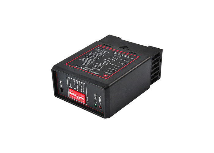
Product Images

Operation and Indicators
During tuning, both green Channel LED and red Power LED illuminate for approximately 2 seconds, after which the green LED turns off. If a loop fault occurs, the Channel LED flashes to indicate the fault. The green Channel LED illuminates when a vehicle is detected passing over the inductive loop. The red Power LED remains on continuously to indicate unit power status.
Configuration Settings
Frequency Adjustment
Frequency can be altered to eliminate interference between neighboring wire loops or loop detectors.
Sensitivity Settings
Four sensitivity selections available, configured via DIP3 and DIP4 switches to determine the inductance change necessary for output.
Automatic Sensitivity Boost
Controlled by DIP5 switch: OFF - Disabled, ON - Enabled. Boosts sensitivity to maximum during vehicle detection and maintains this level while the vehicle is present over the loop.
Filter Mode
Activated by setting DIP6 Switch to "ON" position. Delays reaction time and reduces sensitivity to eliminate environmental interference. Normally disabled with DIP6 Switch in "OFF" position.
Output Relay Configuration
DIP7 OFF: Relay1 and Relay2 energize when vehicle is detected, de-energize when vehicle departs.
DIP7 ON: Relay2 energizes on detection, de-energizes on departure, with Relay1 energizing for 500ms after a 500ms delay.
Presence Time Settings
Configurable via DIP8 Switch: OFF - Limited Presence (10 minutes), ON - Permanent Presence. In permanent presence mode, the detector continuously compensates for environmental changes while a vehicle is present.
Reset Function
The detector automatically tunes to the inductive loop when power is applied. Manual retuning can be initiated by momentarily operating the RESET switch after changing switch settings or moving the detector between installations.
Attention: If the detector isn't working normally, first check the loop and wiring, then adjust frequency or sensitivity settings, and finally try activating filter mode.

 Your message must be between 20-3,000 characters!